

Crankshaft and Camshaft Machines
Our experts have mastered the crankshaft and camshaft machining process with our specialized machines and services.
.webp "Deep Fillet Roller DSC_1112 (1)")
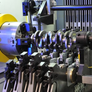
Deep Fillet Rolling
With the light-weighting of automobiles, every component of a vehicle has to be produced with the least amount of mass. This is true for crankshafts. Crankshafts are subject to high stresses and suffer from metal fatigue due to torsion and bending. Too, turbo-chargers on smaller engines produce higher horsepower and torque, thereby increasing metal fatigue.
By using deep fillet rolling, manufacturers can place high residual stresses into the under-cut corners of a crankshaft, thereby increasing the fatigue life of the unit.
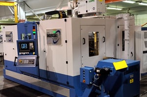
Crankshaft Mill
Crankshaft castings and forgings are produced with stock material intentionally left in to be machined away. This assures the final product will be the exact shape and be properly balanced for high motor RPMs.
One of the initial machining processes of the crankshaft is to mill away the extra iron or steel of the pin journals and main journals.
Crankshaft Mill
Description. Lorem ipsum dolor sit amet, consetetur sadipscing elitr, sed diam nonumy eirmod tempor invidunt ut labore et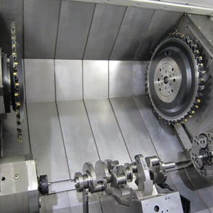
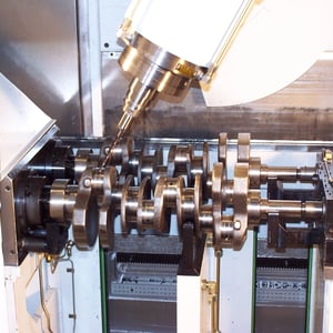
CNC Oil Hole Drill
Crankshafts in an engine need forced oil lubrication for the journal surfaces and the pin-journal surfaces inside the connecting rods. The lubrication delivery is provided by an oil pump in the engine and porting holes from the engine block bearings which pass through the crankshaft cross holes to the connecting rod. These oil holes in the crankshaft need to be produced accurately to assure they lubricate in the correct locations and do not weaken the crankshaft in the zones where it is subject to metal fatigue.
Crankshaft manufacturers need to use a very accurate CNC Oil Hole Drill that can produce these lubrication passages.
Turning
Description. Lorem ipsum dolor sit amet, consetetur sadipscing elitr, sed diam nonumy eirmod tempor invidunt ut labore et
Cam Lobe Machine (CLM) Series
Camshaft manufacturers who produce their product from steel billet commonly use a form of contour cam lobe milling. Milling helps to achieve a near-net lobe profile for surface hardening, final grinding, and polishing. Full depth creep-feed grinding is too time consuming and wastes valuable grinding abrasive perishables to achieve this same near-net profile.
.webp?width=300&name=CLM%20Series%20Cam%20Lobe%20Mill%20(5).webp)